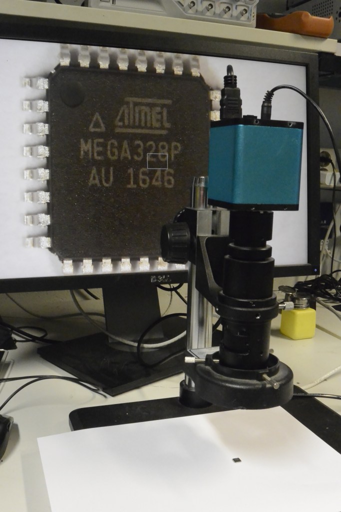
The wave logger required a processing unit to manage the pressure reading, timely organize the reading with a timestamp and finally save them to the memory card. You can think of it as the “CPU”, the “brain” of the sensor. The already 7-year-old project was based on the once very popular ATMEGA 328P MCU, that back in its golden days could be found in many Arduino boards. The chipset world is developing so fast, that by 2021 the Microchip company was no longer producing this atmega, and the leftovers could be only found on some e-bays and some less known mostly Chinese distributor pages, usually with very little to no technical description. I took the risk and ordered atmegas from 2 different eBay users (hoping that one must work) and I proceeded to assemble the board.
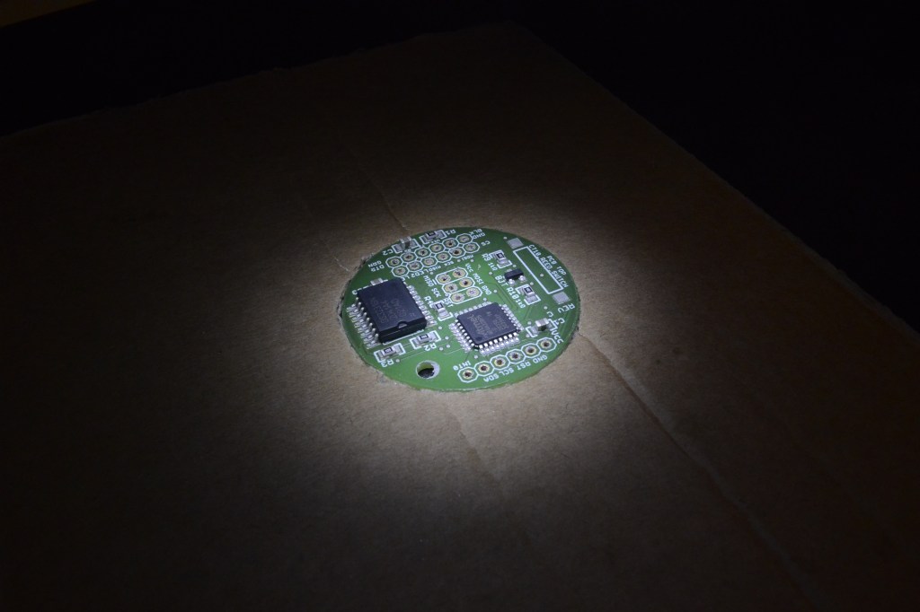


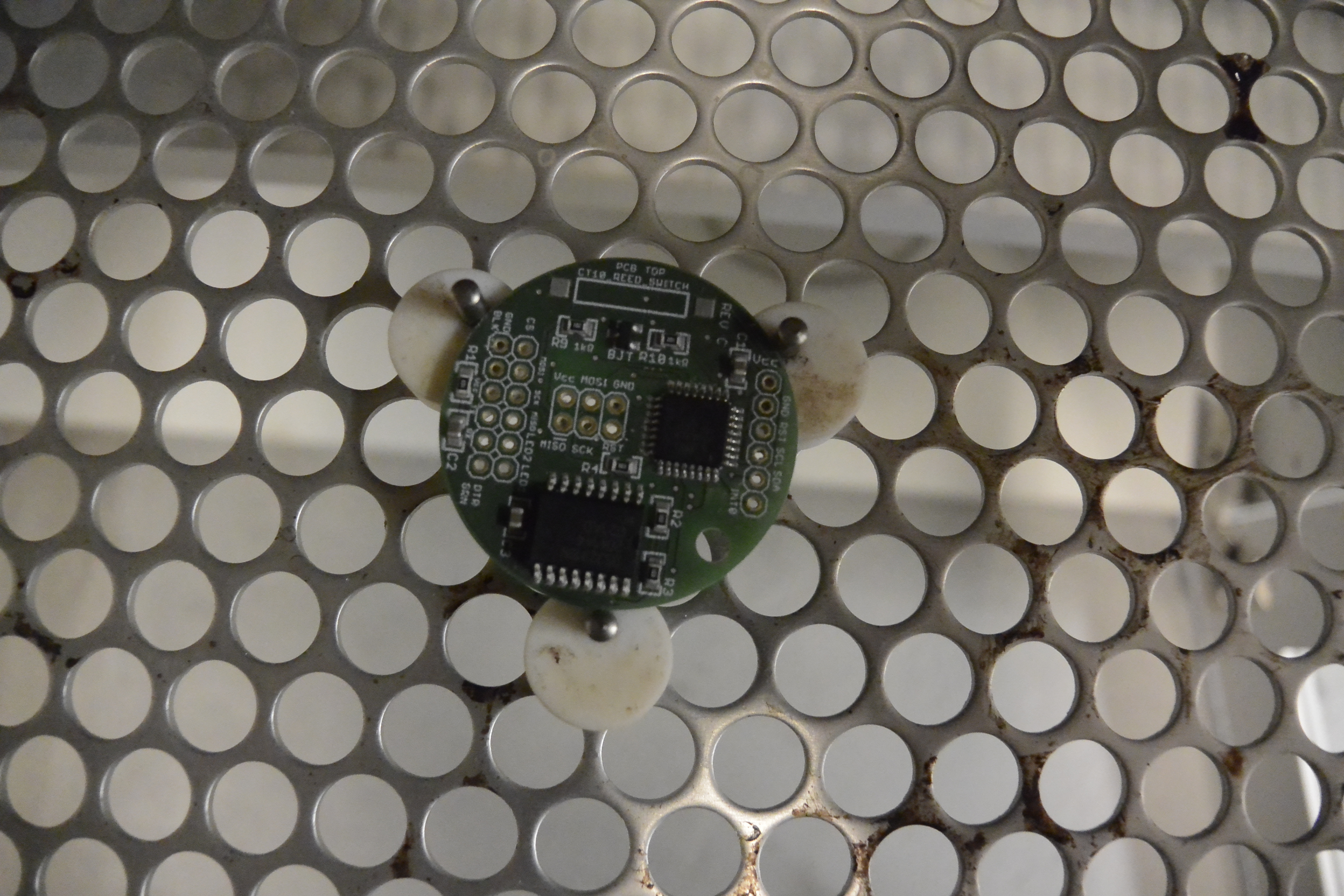
Soldering 64 of 1 mm wide processor leg to the printed layout even using soldering tape and the microscope was a challenge. It turned out that even applying smoothly soldering paste with this precision required several attempts. Anyway, after several minutes in the reflow oven (a more fancy version of an oven to solidify the soldering paste) was ready.
I was pretty excited to first connect to it by Arduino IDE. Tingo sat by my laptop, we connected everything, started the app, and … nothing happen. We checked the cables, and still, nothing. We checked the baud rates, disassembled the connection, and reconnected, checked board schematics, pin layout, the voltage on board, and still, we were getting the same errors over and over again. Now, starting with “bare hardware” is not the easiest thing to do, but if one follows the right instructions it’s doable. Tingo grew suspicious that when trying to install the bootloader the atmega is bricked so we tried to unbrick it. That did not work. We could not even read fuses. We also decided to use different devices for connection: tinyUsb programmer, tutaj finish me. That did not work either. We triple-checked the designs and recalculated the voltage, but still, nothing worked. I did not know where is the problem? My soldering? The design? Atmega?
avrdude: initialization failed, rc=-1
         Double check connections and try again, or use -F to override
         this check.
I wrote an-email to the designer Luke Miller, and to my surprise, he responded by proposing to check the thighs we already checked.
anna:~$ /home/anna/arduino-1.8.5/hardware/tools/avr/etc/avrdude.conf -pm328p -cusbasp -e -Ulock:w:0x3F:m -U efuse:w:0x05:m -U hfuse:w:0xDA:m -U lfuse:w:0xE2:m
avrdude: error: program enable: target doesn’t answer. 1
avrdude: initialization failed, rc=-1
Double check connections and try again, or use -F to override
this check.
avrdude done. Thank you.
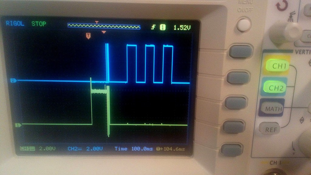
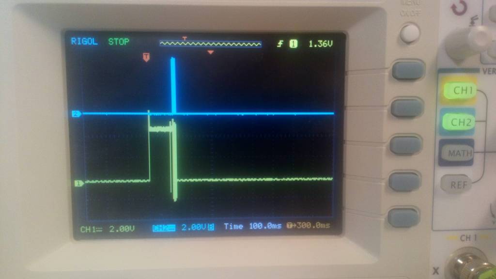
Somebody hinted to use an oscilloscope to test if I receive the right signals. Measuring voltage on the 1 mm legs of atmega was not easy but doable. I executed the measurements and compared them to the old atmega based Arduino boards that I knew were working, I could see the difference, but not draw conclusions.

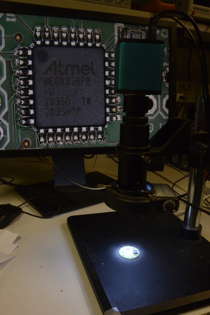
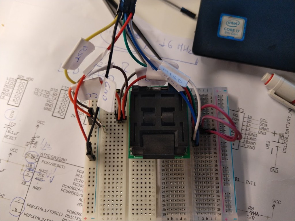
At first, lots of people were willing to help but at a certain point the advice would repeat, I would not progress, and people slowly, one by one would stop answering questions and returning e-mails. I asked the spark fun forum only to get the same tips we already followed. One of my work friends, Andy, hinted to me that there are such things as “break out boards” that allow for creating a wired prototype of the board, a “Frankenstein” version of the project just to make sure it actually works. I did have a working atmega from an old Arduino board. After some long googling I found and bought an SMT test socket.
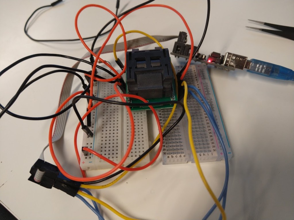
The real power of Bitraf is not just equipment, but the people that make this place alive. I met Dag and Jensa, experienced, passionate guys with who I could discuss my project. Dag was like a bottomless testing idea generator. Jensa had a very practical approach. He would point out, that these days, even as much as 20% of Chinese cables (yes it’s not a spelling mistake) are not working. He also decided to re-create my setup, he used his tiny-USB device to connect to the board, and …. magically the atmega responded!
2 guilty were found: the atmega (yes) and the device I was using to talk to atmega from my laptop. About atmega I was not surprised, I was already suspicious, just needed proof. But a “cable”? For some weird reason, some boards would work with USB tiny, and some wouldn’t. Don’t ask me, just the behavior I have observed
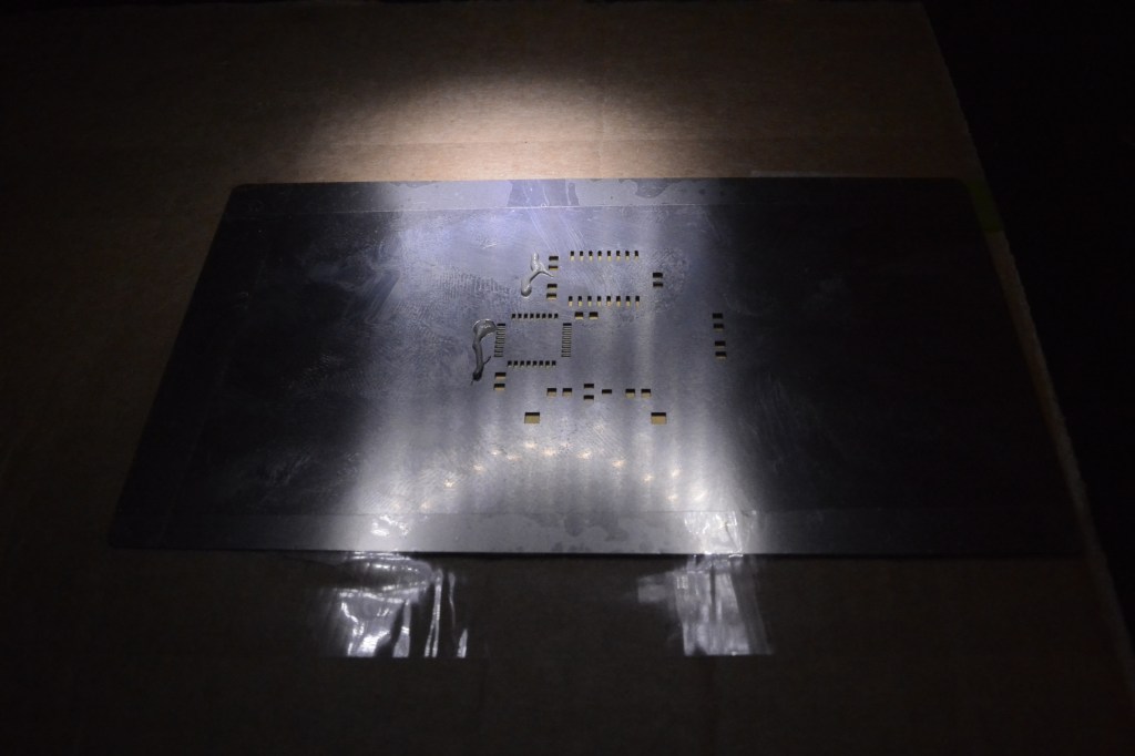
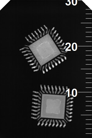
From now on things got smoother. Another person at Bitraf – Elias told me they have some stashed original atmegas in one of the million boxes in Bitraf – so I had my supply and I could assemble more boards. I was still curious what could I do to prevent it? I read somewhere that an actual X-ray would be needed to figure out the real or fake atmega. While visiting my dentist, I asked her for a favor. She was cool to X-ray my chips wondering what dose of radiation she should use (used the one for kids) – here are the results. Which one would you guess is the real, which is the fake one?
I am not electronics engineers so I cannot know if the atmega could be counterfeit or knot. My dentist used medical x-ray not the technical x-ray if they exist – so we also cannot know for sure. All i know is that the device was not responding, the osciloscope results would be different from working atmega.
Through all my practice I have learnt that the signatures of working ATmega were:
| without bootloader | E:07 | H:D9 | L:62 |
| after successful booltader load | E:05 | H:D7 | L:E2 |


Leave a comment